


How to Determine Span, Runway Length, and Hook Coverage for a Free-Standing Overhead Crane
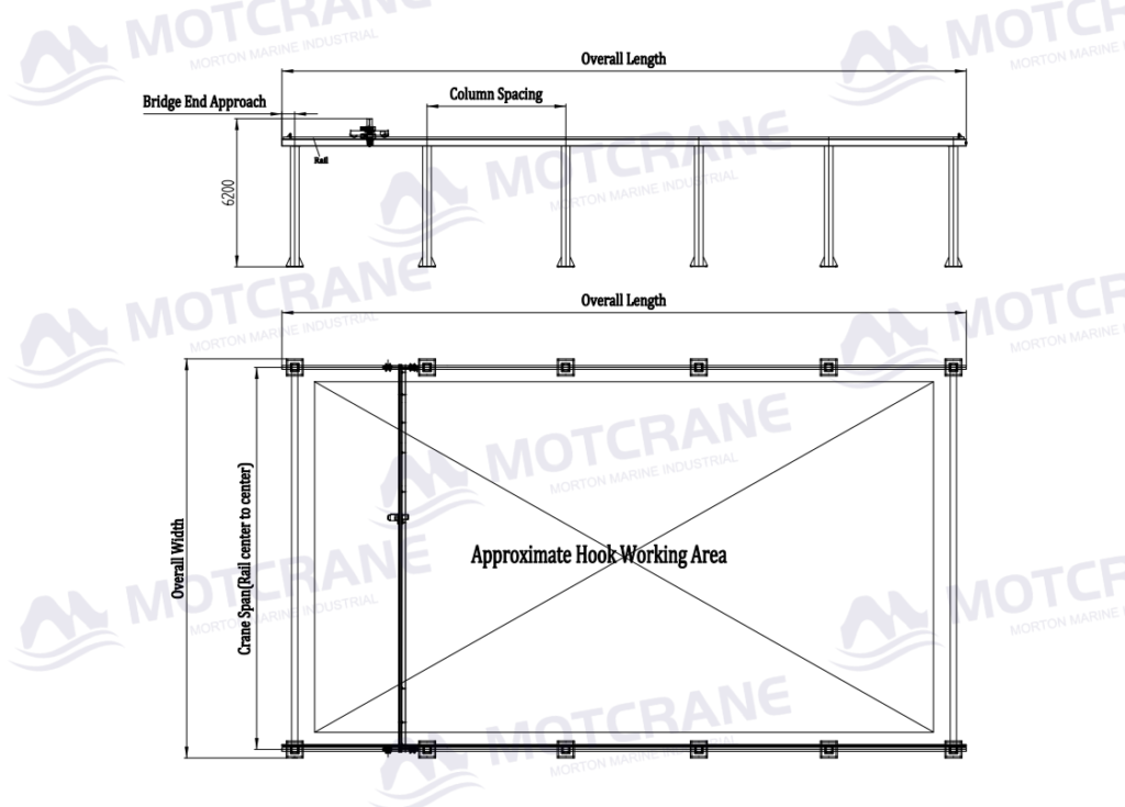
If a free-standing overhead crane requirement is specified simply as “6 m × 30 m,” the design team still cannot determine the correct crane dimensions. The first question is what this size actually represents: the overall installation dimensions, the crane span and runway length, or the actual working area that the hook must cover. For a free standing overhead crane span, the starting point should be the required hook working width rather than the requested overall crane width.
These dimensions are not interchangeable. If 6 m × 30 m describes the required hook working area, the final crane span and runway length will normally be larger. If it already represents the maximum space available for installation, the usable hook working area will be smaller.
The Required Hook Working Area should be defined before the crane span or runway length. From there, the layout can be developed through hook approach, crane span, runway length, column layout, and Overall Installation Dimensions. If the project team is still deciding whether an independent support structure is suitable, see our guide on when a free-standing overhead crane is the right choice for an existing workshop.
1. Overall Crane Dimensions, Span, and Hook Working Area Are Different Measurements
A free-standing overhead crane involves three different dimensional levels: the Required Hook Working Area, which defines where the hook must operate; the Crane Span and Runway Length, which define the main crane and runway geometry; and the Overall Installation Dimensions, which include the columns, runway beams, end structures, and required clearances.
For example, a project may specify a crane size of 6 m × 30 m. If the 6 m refers to crane span, the actual hook working width will be smaller because the trolley cannot travel all the way to both runway centerlines.
If an initial quotation or layout only shows “6 m × 30 m,” the buyer should first confirm what those two dimensions represent before approving the arrangement.
2. The Actual Hook Working Area Is the Starting Point for Dimensional Design
Before determining the crane span or runway length, identify the four extreme positions that the hook must reach:
- the leftmost lifting point;
- the rightmost lifting point;
- the foremost lifting point;
- the rearmost lifting point.
These four positions define the:
Required Hook Working Width × Required Hook Working Length
The boundary should follow the actual production process rather than the overall workshop size. Oversizing the working area increases bridge, runway, and support-structure size without improving handling, while undersizing it may leave machine loading points, maintenance positions, or transfer locations outside the hook’s reach.
3. Relationship Between Hook Working Width and Crane Span
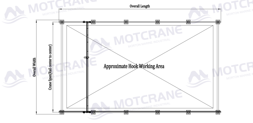
When determining a free standing overhead crane span, the required hook working width and the Hook Side Approach at both ends must be considered together. Crane span normally refers to the distance between the centerlines of the running rails on both sides.
The hook, however, cannot travel across that full distance.
The hoist and trolley require a certain Hook Side Approach at each end of the bridge. The actual value depends on the hoist, trolley, girder arrangement, and end clearances.
The relationship can be understood as:
Required Crane Span ≈ Hook Working Width + Left Hook Approach + Right Hook Approach
The required allowance depends on the final hoist, trolley, and bridge arrangement rather than on a fixed value.
When reviewing the general arrangement drawing, the buyer should not confirm the span alone. The Hook Side Approach and actual Hook Working Width should be checked at the same time.
A span can be technically correct while the hook coverage is still insufficient for the intended workstation.
4. Relationship Between Hook Working Length and Runway Length
When determining runway length, the required hook working length and the Bridge End Approach at both ends must be considered together. When the bridge reaches either end of the runway, the bridge end carriages, buffers, end stops, and required clearances occupy part of the available length.
For this reason:
Hook Working Length ≠ Runway Length
The basic relationship is:
Required Runway Length ≈ Hook Working Length + Front End Approach + Rear End Approach
Runway Length describes the structural length of the runway system, while Bridge Travel describes how far the crane bridge can actually move. If the process requires 24 m of usable hook travel, the buyer should confirm the actual Bridge Travel rather than assume that a 24 m runway provides the same usable distance.
5. Column Layout Should Be Adjusted After the Hook Working Area Is Defined
A free-standing overhead crane requires independent support columns, so their positions must account for machines, electrical cabinets, forklift aisles, doors, maintenance zones, trenches, and access routes rather than simply using whatever floor space is available.
Moving one column changes the spacing between supports. That can change the runway-beam span and its load conditions, which may in turn affect the supporting structure. Significant changes to column spacing may also affect support reactions and foundation requirements. See our guide to free standing overhead crane foundation requirements.
The more reliable sequence is:
Hook Working Area → Crane Span and Runway Length → Column Layout
After column positions are adjusted, the hook coverage should be checked again, especially in existing workshops where machinery and access routes are already fixed. For additional technical guidance on overhead crane design and runway systems, refer to the Crane Manufacturers Association of America (CMAA).
6. Final Dimensions Should Be Confirmed on the General Arrangement Drawing
A workable General Arrangement Drawing should answer two questions at the same time:
Can the hook reach every required lifting position?
and
Can the complete crane structure fit within the available installation space without interfering with equipment, walls, aisles, or doorways?
The General Arrangement Drawing should clearly show the required hook working area, crane span, runway length, hook approaches, column spacing, and overall installation dimensions.
The final crane dimensions should therefore not be confirmed from a quotation line such as “6 m × 30 m” alone.
For a free-standing overhead crane project, MOTCRANE can define the required hook working area, then develop the crane span, runway length, column layout, and General Arrangement Drawing around the selected bridge and hoist arrangement. If the required hook working area is already known, contact MOTCRANE to develop the layout for confirmation.
This helps identify inaccessible lifting positions, column conflicts, insufficient runway travel, or oversized installation dimensions before fabrication begins. When confirming a free standing overhead crane span, runway length, hook approach, and actual hook coverage should be reviewed together rather than as isolated dimensions.
Required Hook Working Area → Hook Approach → Crane Span / Runway Length → Column Layout → Overall Installation Dimensions



 English
  Russian
  French
  Spanish
  Arabic
  Indonesian
  Japanese