


Lifting Is Only Half the Job: How Hydraulic Gantry Cranes Move Heavy Loads Sideways
Hydraulic gantry crane side shift addresses a common installation problem: a crane may have enough lifting capacity to raise a heavy machine but still be unable to place it directly onto its foundation. If your pick-up position and final installation position are offset across the header beam, powered side shift allows the suspended load to move laterally for final positioning.
The design questions are straightforward: how far must the load move, can the trolley travel that distance, and can the complete system carry the load throughout the operation?
1. When Is Powered Side Shift Needed?
Hydraulic gantry crane side shift becomes necessary when a suspended load must move along the header beam to reach its installation position.
For example, existing columns, foundations or production equipment at your site may prevent a hydraulic gantry crane from being positioned directly over a press foundation. The machine can be lifted from its transport supports, but its lifting position does not line up with its final location.
Hydraulic lifting provides vertical movement, while the travel units beneath the gantry move the complete system along its skid tracks. Neither movement, on its own, corrects an offset along the header beam. Powered side shift provides that final lateral adjustment. If the load can be lifted and lowered directly into position, powered side shift is unnecessary. It may also be unnecessary when longitudinal travel alone can bring the load into alignment with the installation point.
2. How Does Hydraulic Gantry Crane Side Shift Work?
Powered side shift moves the suspended load by driving the trolleys along the header beams; the gantry itself does not travel sideways.
A typical four-point MOTCRANE configuration has four hydraulic lifting units, two header beams and four powered side-shift trolleys. The lifting units raise and support the structure. The trolleys connect to the rigging and move the load laterally along the beams.
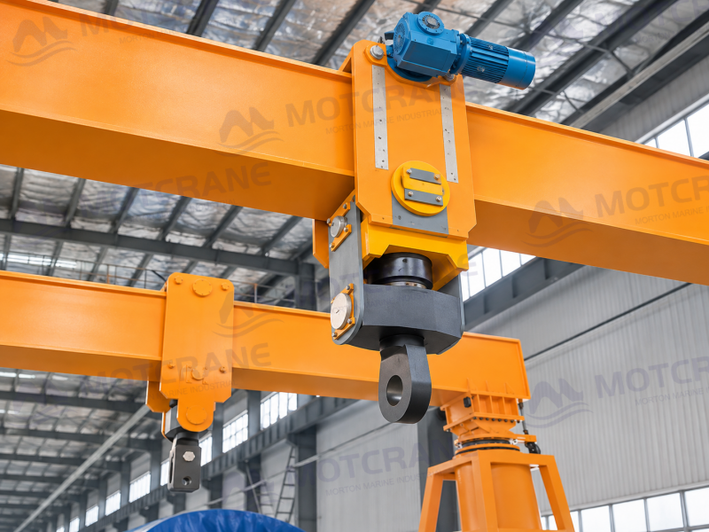
In the operating sequence described for this configuration, the load is raised to the required height, lifting and longitudinal travel are stopped, and the system is brought to a stable condition before powered side shift begins. Once the load reaches its target position, side-shift movement stops before lowering.
The side-shift drive is managed through the crane’s centralized control system. Load movement is permitted only within the system’s rated capacity and specified operating conditions.
Some hydraulic gantry configurations use manually adjustable lifting points instead of powered trolleys. Manual positioning and powered movement under load are different capabilities; your RFQ should state explicitly whether loaded side shifting is required.
3. How Do You Determine the Required Side-Shift Travel?
To determine hydraulic gantry crane side shift travel, start with the difference between the pick-up and installation positions measured along the header-beam direction. Then verify that the available trolley travel and site clearance can accommodate the movement.
First, show the pick-up position, installation position, beam orientation and lifting-point locations on the same plan drawing for your project, using one reference datum. The displacement along the beam axis establishes the required lateral movement.
Next, check the effective travel of each trolley. Header-beam overall length is not the usable trolley stroke: trolley dimensions, end structures, mechanical stops and minimum spacing between trolleys reduce the available range.
Finally, verify the complete travel path. The load and rigging must clear gantry legs, building columns, foundations and nearby equipment, with sufficient vertical clearance at the planned lifting height.
A proposed side-shift stroke is acceptable only when the required displacement, usable trolley travel and physical clearances all agree.
4. What Must Be Checked Before Side Shifting Under Load?
Load Weight and Center of Gravity
The load weight, center of gravity and lifting-point arrangement determine the forces carried by individual trolleys. Uneven load distribution means that dividing the total weight equally between four lifting points is not a valid design assumption.
Trolley loads and the corresponding gantry-leg reactions must be checked for the planned load positions.
Header-Beam Capacity Throughout the Travel Range
The header beams must be designed for the load at every permitted trolley position, not just at the initial lifting position.
Some beam designs use position-dependent capacity charts. MOTCRANE’s stated design objective is to retain the full system-rated capacity throughout the specified effective side-shift travel, subject to the permitted trolley arrangement, individual point loads and other rated operating conditions.
For illustration, a 200-tonne system designed and verified to this requirement would retain a 200-tonne total system rating at each approved side-shift position. This does not mean that any one trolley is rated for 200 tonnes, or that beam forces and support reactions remain unchanged.
Coordination of Multiple Trolleys
Multiple trolleys must move in the permitted control mode so that the rigging arrangement and load attitude remain within the approved limits. Uncoordinated trolley movement can change lifting-point forces and introduce unwanted load inclination or distortion.
Permitted individual and coordinated movements must be defined in the system controls and operating procedure.
Ground, Skid Tracks and Support Conditions
The supporting surface and skid-track arrangement must carry the changing gantry-leg reactions throughout the side-shift movement.
Ground bearing capacity, track layout and support conditions therefore need to be verified against the actual load case, not only the load at the initial lifting position.
5. What Information Should Be Included in an RFQ?
For hydraulic gantry crane side shift applications, your RFQ should define the complete load path and the intended lateral movement, rather than specifying only a crane capacity and beam length.
- Load details: total weight, overall dimensions, center of gravity, lifting-point positions and rigging arrangement.
- Movement: pick-up and final installation positions, beam orientation and required lateral displacement.
- Site constraints: plan drawings, available headroom, obstructions, leg positions, ground conditions and skid-track layout.
- Operating sequence: whether the project also requires longitudinal travel, and the planned order of lifting, traveling, side shifting and lowering.
These details allow the header beams, trolley travel, lifting-point ratings and overall system configuration to be checked against the job.
FAQ
Q1. Can powered side shift be added to an existing hydraulic gantry crane from another manufacturer?
Potentially, yes, but it requires a project-specific retrofit. The existing lifting lugs or suspension fittings generally need to be replaced, and new powered trolleys designed to match the original header-beam geometry and structural capacity. The modified arrangement also requires verification of the load path, drive and centralized control integration before use.
Q2. Does powered side shift need a separate controller?
Not on the MOTCRANE configuration described here. Hydraulic lifting, powered side shift and longitudinal travel are managed through a centralized control system, with operating modes defined for the respective functions.
Q3. Can powered side shift be used outdoors?
Yes, provided the configuration is designed for the site conditions. Wind limits, environmental protection, ground bearing capacity, skid tracks and the approved operating restrictions must all be considered.
Conclusion
Hydraulic gantry crane side shift does not increase lifting capacity; it enables a suspended heavy load to reach an installation position that vertical lifting and longitudinal travel alone cannot serve.
Share your load data, lifting-point arrangement, site plan and intended movement path with MOTCRANE. These are the inputs needed to engineer the header beams, side-shift trolleys and integrated hydraulic gantry system for the job.



 English
 Russian
 French
 Spanish
 Arabic
 Indonesian
 Japanese